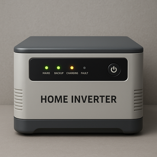
A home Inverter is an electronic device that converts direct current (DC) into alternating current (AC). It is widely used in solar power systems, uninterruptible power supplies (UPS), variable frequency drives (VFDs) for motors, and many other applications.
To explain clearly, let’s break it down step by step:
1. Why Inverters Are Needed
- Many power sources like batteries, solar panels, and fuel cells produce DC electricity.
- Most appliances, household devices, and the electric grid run on AC power (typically 50 Hz or 60 Hz sinusoidal AC).
- The inverter acts as the bridge, converting DC → AC.
2. Basic Working Principle
At its core, an inverter works by rapidly switching DC input polarity to create an alternating output.
The process involves three main stages:
DC to Pulsating AC (Switching Stage)
- Semiconductor switches (like IGBTs, MOSFETs, or BJTs) turn the DC supply ON and OFF in a specific sequence, generating a square wave output.
- This alternating switching creates a basic form of AC.
Waveform Shaping (Pulse Width Modulation – PWM)
- The raw square wave is too rough for most applications.
- To refine it, inverters use PWM control, where the switches turn on and off at high frequency but with variable-width pulses.
- The average voltage of these pulses follows the shape of a sine wave.
Filtering (LC Filters or Transformers)
- After PWM generation, the output passes through filters (inductors and capacitors).
- These components smooth the waveform, removing high-frequency harmonics, producing a clean sinusoidal AC output.
3. Functional Components of an Inverter
- DC Source: Battery, solar panel, or rectified power.
- Switching Devices: MOSFETs/IGBTs controlled by logic signals to alternate current flow.
- Controller Circuit (PWM Generator): Microcontroller or DSP that generates precise switching signals.
- Driver Circuit: Amplifies control signals to drive power transistors.
- Filter Circuit: Smoothens the waveform into a sinusoidal AC.
- Output Transformer (optional): Adjusts the voltage level (e.g., 12V DC to 220V AC).
4. Types of Inverters by Output Waveform
Square Wave Inverter
- Simplest and cheapest.
- Output: square wave (lots of harmonics, not suitable for sensitive electronics).
Modified Sine Wave Inverter
- Approximation of a sine wave using stepped square waves.
- Better than a square wave, but still not pure.
- Common in low-cost UPS and small inverters.
Pure Sine Wave Inverter
- Closest to the utility grid AC.
- Achieved using advanced PWM and filtering.
- Ideal for sensitive equipment (computers, medical devices, AC motors).
5. Functions of an Inverter
- Power Conversion: Converts DC from batteries or solar panels into usable AC.
- Grid Connection: Synchronizes renewable energy sources with the utility grid.
- Voltage Regulation: Maintains stable output voltage and frequency.
- Energy Efficiency: Improves utilization of renewable energy.
- Backup Power: Provides an AC supply during power outages (UPS systems).
- Motor Control: VFD Home Inverter regulates the speed/torque of motors by varying frequency and voltage.
6. Example of Operation (Simplified)
Imagine a 12V DC battery connected to an inverter:
- The inverter uses MOSFET switches to alternately connect the battery’s positive and negative terminals to the load.
- By switching fast enough, it creates an alternating current across the load.
- With PWM and filtering, this alternating current is shaped into a 50Hz or 60Hz sine wave at 220V or 110V AC, suitable for household appliances.
A home Inverter works by electronically switching DC power at high speed to mimic an AC waveform, then using PWM and filtering to refine it into a usable sinusoidal output. Its main function is to make DC sources compatible with AC-based systems, which is essential for modern power distribution and renewable energy integration.


